
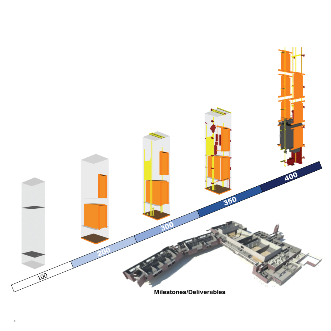
LOD 100
The Model Element may be graphically represented in the Model with a symbol or other generic representation, but does not satisfy the requirements for LOD 200. Information related to the Model Element (i.e. cost per square foot, tonnage of HVAC, etc.) can be derived from other Model Elements. BIMForum Interpretation: LOD 100 elements are not geometric representations. Examples are information attached to other model elements or symbols showing the existence of a component but not its shape, size, or precise location. Any information derived from LOD 100 elements must be considered approximate.
LOD 200
The Model Element is graphically represented within the Model as a generic system, object, or assembly with approximate quantities, size, shape, location, and orientation. Non-graphic information may also be attached to the Model Element. BIMForum interpretation: At this LOD elements are generic placeholders. They may be recognizable as the components they represent, or they may be volumes for space reservation. Any information derived from LOD 200 elements must be considered approximate.

LOD 300
The Model Element is graphically represented within the Model as a specific system, object or assembly in terms of quantity, size, shape, location, and orientation. Non-graphic information may also be attached to the Model Element. BIMForum interpretation: The quantity, size, shape, location, and orientation of the element as designed can be measured directly from the model without referring to non-modeled information such as notes or dimension call-outs. The project origin is defined and the element is located accurately with respect to the project origin.

LOD 350
The Model Element is graphically represented within the Model as a specific system, object, or assembly in terms of quantity, size, shape, location, orientation, and interfaces with other building systems. Non-graphic information may also be attached to the Model Element. BIMForum interpretation. Parts necessary for coordination of the element with nearby or attached elements are modeled. These parts will include such items as supports and connections. The quantity, size, shape, location, and orientation of the element as designed can be measured directly from the model without referring to non-modeled information such as notes or dimension call-outs.

LOD 400
The Model Element is graphically represented within the Model as a specific system, object or assembly in terms of size, shape, location, quantity, and orientation with detailing, fabrication, assembly, and installation information. Non-graphic information may also be attached to the Model Element.
BIMForum interpretation. An LOD 400 element is modeled at sufficient detail and accuracy for fabrication of the represented component. The quantity, size, shape, location, and orientation of the element as designed can be measured directly from the model without referring to non-modeled information such as notes or dimension call-outs.
LOD 500 [NOT USED]
The Model Element is a field verified representation in terms of size, shape, location, quantity, and orientation. Non-graphic information
may also be attached to the Model Elements. BIMForum interpretation. Since LOD 500 relates to field verification and is not an indication of progression to a higher level of model element geometry or non-graphic information, this Specification does not define or illustrate it.