

Antenna Structures and Design
Axicom Structures
The expansion of Axicom sub-licence reference design, to include 5G AAUs / additional equipment at eJV Axicom sites, is subject to agreement between the Operators and is currently out of scope for the eJV 5G project.
Headframe Structures
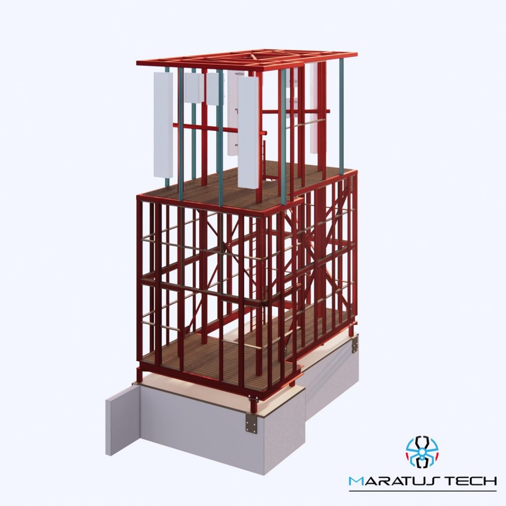
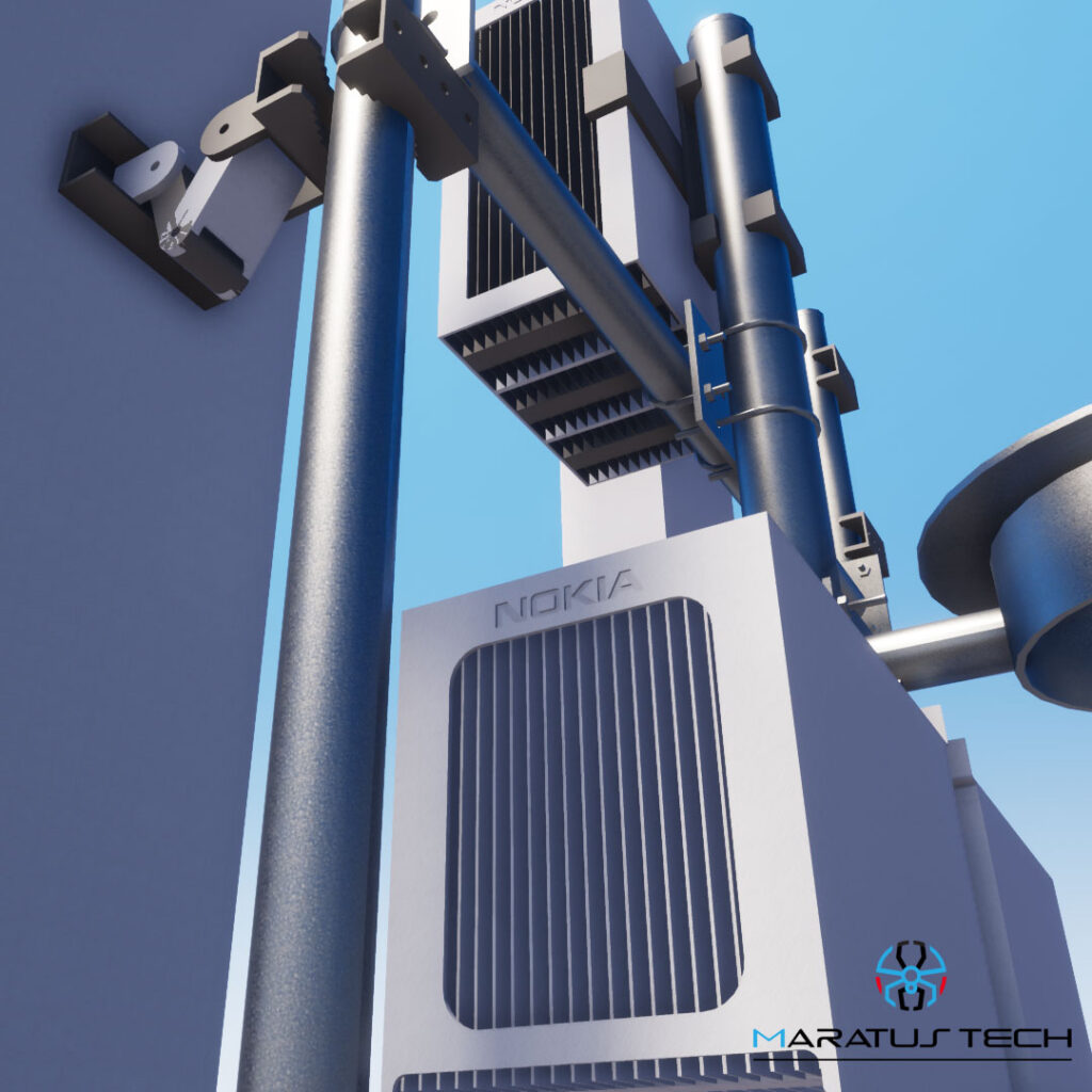
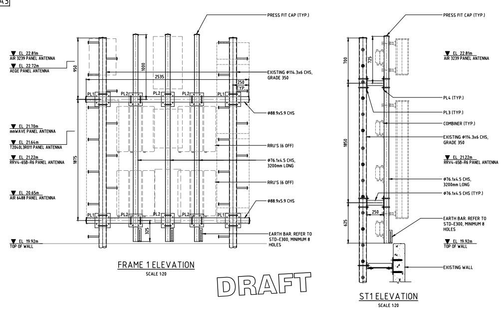
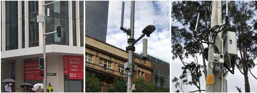
At monopole and tower sites, the mounts for the AAUs, passive antennas and RRUs are generally designed to be on headframes or similar structures (turret-mounts, clamp-mounts, etc), while microwave antennas are usually mounted directly to the monopole/tower. Different structures will require variations in the design of mounting arrangements. Some sites may have a large existing headframe that will allow three or four antenna mounts to be located across the face for each sector.
Suppliers are to consider designing sites based on swapping the headframe or sector to a fully pre-built and pre-rigged headframe (with antennas AAUs & RRUs) or sector mount assembly to minimise outage and plant hire times and to increase standardisation and quality, where viable.
Alternatively, the existing headframe and mounts can be utilised mounting AAUs pole-mounted above or below the level of the headframe, outrigged to the sides or three long mounts, two extra-long mounts, or mounting the AAUs immediately below the headframe, strapped to the pole, or any other mounting mechanism that may apply to the site, refer to Section 3.4 for some examples of mounting arrangements.
Where expansion to the existing headframe is required, the Supplier must assess whether the complete headframe should be replaced or the existing one upgraded.
Existing sites with existing smaller headframes or turret style mounts may require redesign to achieve SU RSD-0.

Headframe-Structures
Monopoles, Towers and Guyed Masts
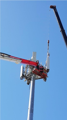
A structural analysis must be performed and recorded prior to work commencing (see Section 12.7.2 below). It is both operators’ policy that the analysis and any resulting strengthening design must be performed by the original tower/monopole supplier as they have the most accurate records and load information relating to the structure, have detailed models and understanding of the structure and their involvement will reduce risk to the operators. This analysis will include all existing loading, reserved load capacity and the proposed loads to determine the loading of the structure. The standard structural certificate included in Section 16is to be supplied in the handover documents.
Any strengthening work should be complete before upgrade work on the structure commences, unless a temporary arrangement to progress with the Sit Upgrade has been agreed with the Host Operator.

Towers and Guyed Masts
Rooftops
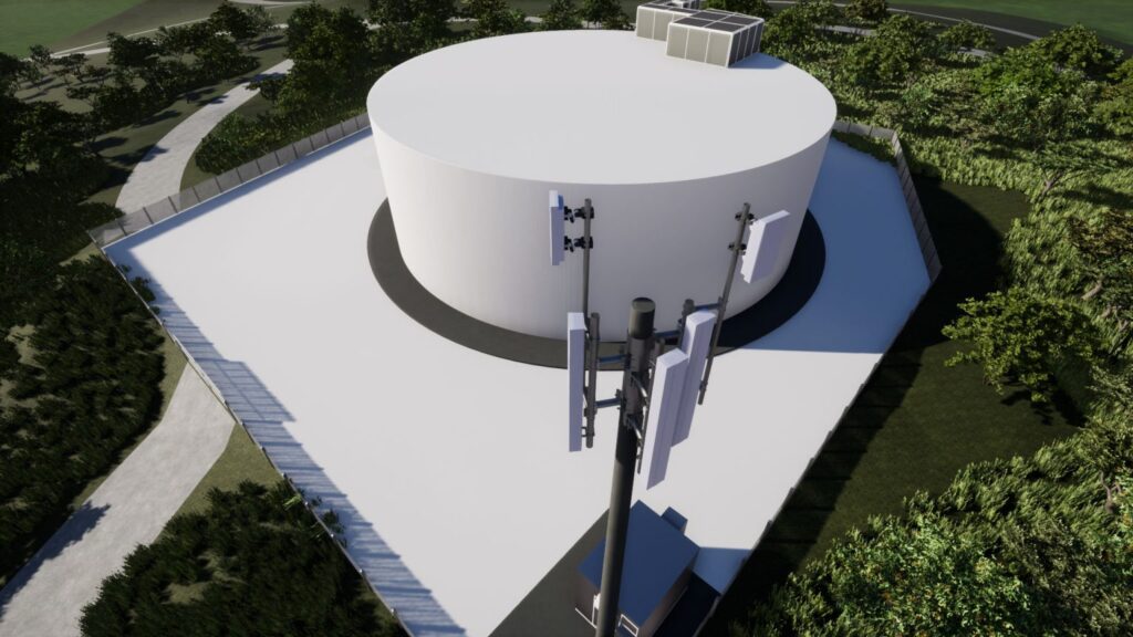
There is a large variation in the types of rooftop sites that are used for eJV sites, resulting in many different mounting arrangements. Rooftops with large lease areas on large buildings will present opportunities to have three or four antenna mounts per sector, to achieve RSD-0. Designs for rooftop sites must consider rooftop walkways, unprotected edges, handrails, parapets, roof membrane and water-proofing, cable ladder routing, weak and brittle brickwork walls, aged and delicate roofing materials, neighbouring rooftops, etc.
As noted in previous sections, RSDs with a large amount of equipment such as RSD-0 may cause an undesirable visual impact to low 2-storey buildings and structures due to the dominance of the installation when compared to the scale of the existing building or structure. In such cases the Step-back Decision Matrix in Section 3.3 is to be applied.
Consideration is also to be given to ensuring that low-level rooftop sites are designed to have mounts that are:
• symmetrical in form after antennas are installed,
• connections are detailed to appear streamlined and do not appear irregular with a mess of U-bolts, slotted holes, cross members and back-braces everywhere,
• have a consistent visual form,
• diagonal back braces are minimised in height,
• possibly utilise a cluster style mount with all sectors in the one location,
• utilise a 4-sided cluster mount for 4-sector sites,
• flush-mount the antennas to a wall or column or other part of a building, where possible,
• install RRUs. Break-out box and combiners lower down on the roof so that they are hidden when viewed from street level,
• utilised architectural forms of the building or protrusion from the building to lessen the impact, shroud or camouflage the site.
Where a sector or site is in clear direct view from an adjacent residence or from one across the road, the above measures must be considered to lessen the visual impact of the site, where practical.
All cantilever mounts should have a back-brace to reduce long-term fatigue in the lower section of the mount and baseplate. To reduce visual impact, the brace need not be attached to the upper section of the cantilever mount; attachment at 1/2 or 1/3 height may be sufficient. Strength and susceptibility to vibration (low natural frequency, <=1Hz) must also be taken into account for mounts, walkways, etc.


Way cool! Some very valid points! I appreciate you penning this post plus the rest of the site is also really good. Dorian Kit Inga