
Blog
Related Posts
15
Apr
BIM in the Telco industry
BIM, or Building Information Modeling, is a process that involves creating a digital representation of a building...

18
Mar
5G Component list for eJV telco sites
Manufacturer
Category
Part number
Frequency
3GPP Band(s)
Supplier Band/Subband
Height
Width
Depth
Nokia
RRU
AHHB
2600
7
7
336
295
140...
09
Mar
Telecom Shroud Cover
Antenna Shroud means the three-sided cover that is mounted at the base of the antenna to conceal the appearance o...
22
May
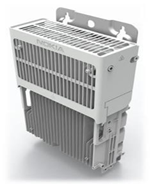
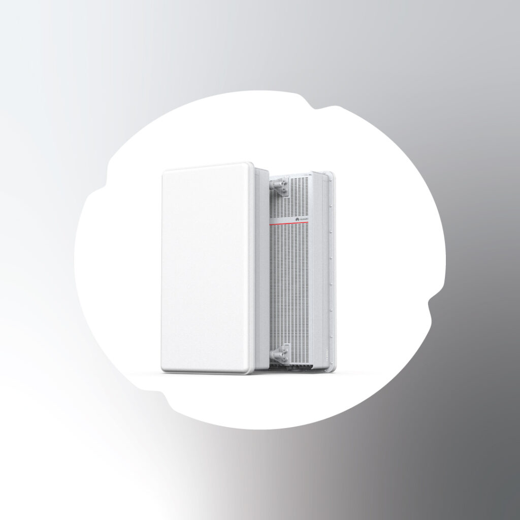
AHPCDB AirScale RRH 2T4R B5,8, and 28 240W
Technical Data
SpecificationDetailsStandard3GPP sub-bands...
22
May
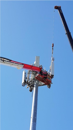
Why use a Sector Assembly?
Increased Safety
Less time working at height, Less hi...

05
Mar
Space Structure
The simplest form of space frame is a horizontal slab of interlocking square pyramids and tetrahed...
25
Apr
Structure Design in the Telecom industry
Workflow of structure design in the telecom industry
Plan

26
Dec
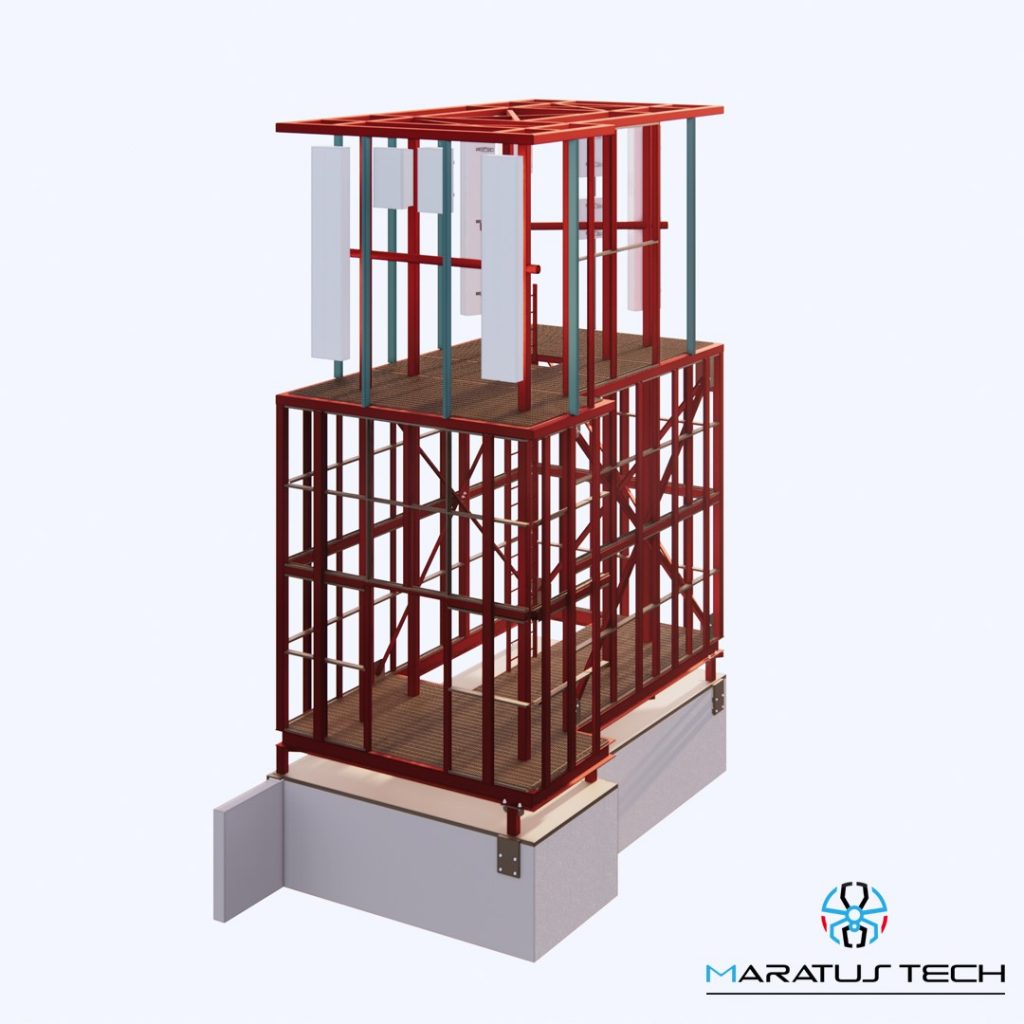
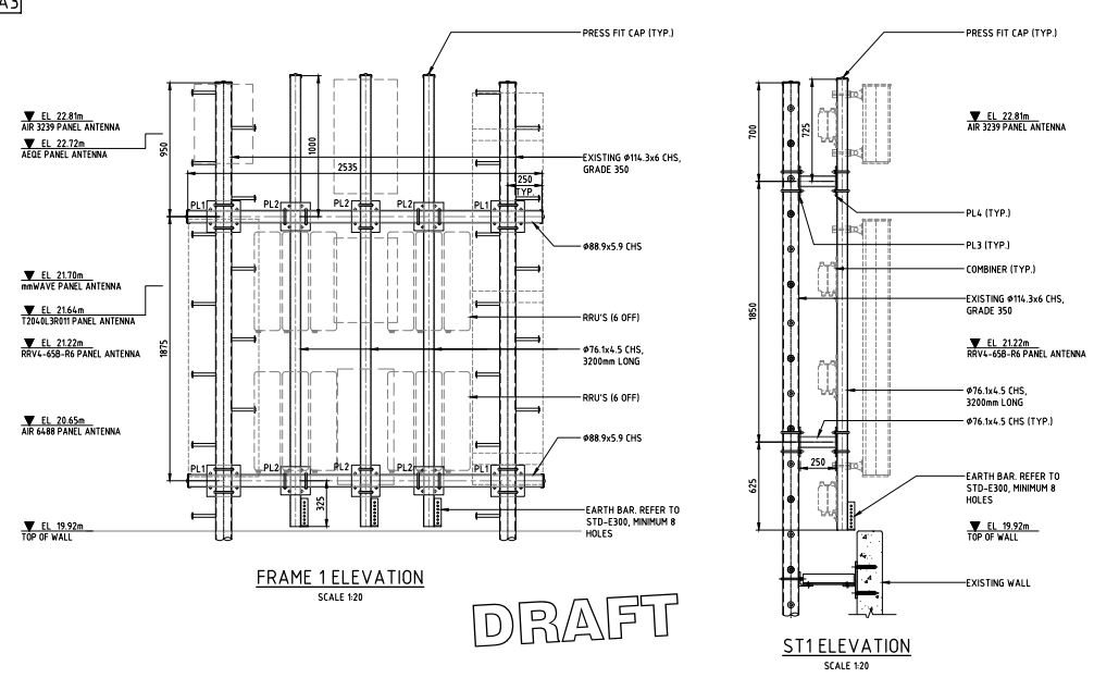
Colar H-Frame Structure
Colar H-Frame Structure
Vodafone 5G upgrade by Nokia Equipment

28
Sep
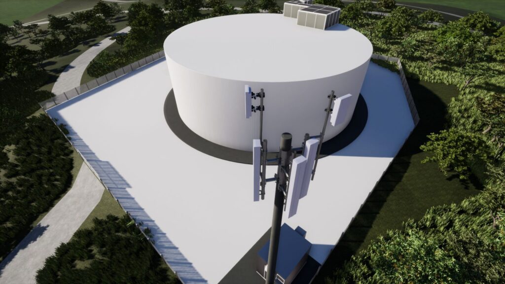
Antenna Structures and Design
Antenna Structures and Design
Axicom Structures
The expansion of Axicom sub-licence reference design, to include 5G AAUs / addit...
23
Sep
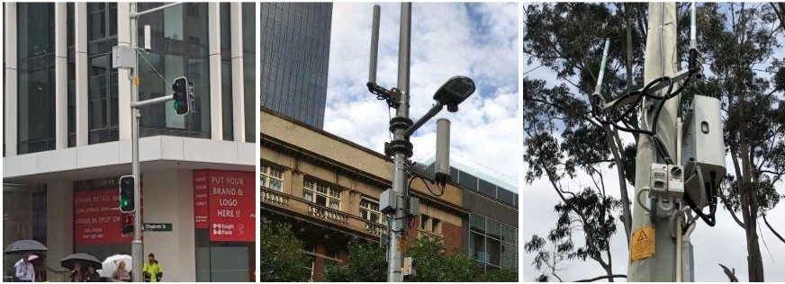
what is small cell ?
what is small cell ?
A small cell is a low powered mobile base station designed to provide mobile phone coverage within an area of appr...
15
Sep
09
Sep
5G site design by Revit
New 5G site design project by Revit in ACT Australia
Description
Telecom Equipment family design in Revit
Site Topo...