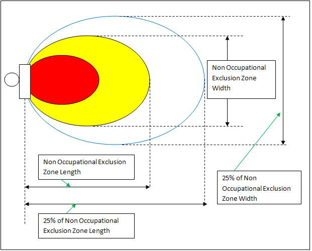
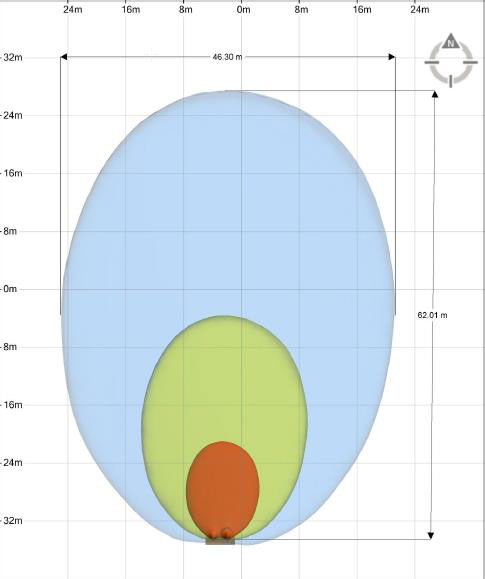
The following nine examples of EME plumes can be used as a guide to help understand the possible size of both the Non Occupational exclusion zones as well as the 25% escalation trigger point for publically accessible areas at feasibility stage. In particular, the following diagrams should be used as a guide for RF engineers when filling out the EME tab in the feasibility document. In reality there are many different scenarios that will give different exclusion zone sizes and it is impossible to document all cases. This document includes 6 scenarios from the absolute worst case down to a typical existing JV. All examples use 2 x 12 port antenna mounted 2.2 meters apart to replicate the report created by an external vendor earlier in the project. It should be noted that changing to 10 port antenna or changing the horizontal separation by amounts less than a couple of meters will not significantly change the size of the EME zones. Examples 3, 4 and 5 are the most typical for this project.
• Example 1
- Worst Case EME Configuration
- All Technologies/Bands using RRU’s
• Example 2
- All Technologies included
- Low band technologies using feeder solution
- High band technologies using RRU’s
• Example 3
- Removed LTE700 and LTE2600 for both carriers
- Low band technologies using feeder solution
- High band technologies using RRU’s
• Example 3 B
- Removed G1800, LTE700 and LTE2600 for both carriers
- Low band technologies using feeder solution
- High band technologies using RRU’s except U2100
• Example 3 C
- Removed G1800, LTE700 and LTE2600 for both carriers
- Low band technologies using feeder solution
- High band technologies using RRU’s except U2100
- Voda LTE1800 2 way MIMO only